SIGGRAPH 2017 Paper- Spectral and Decomposition Tracking for Rendering Heterogeneous Volumes
Some recent work I was part of at Walt Disney Animation Studios has been published in the July 2017 issue of ACM Transactions on Graphics as part of SIGGRAPH 2017! The paper is titled “Spectral and Decomposition Tracking for Rendering Heterogeneous Volumes”, and the project was a collaboration between the Hyperion development team at Walt Disney Animation Studios (WDAS) and the rendering group at Disney Research Zürich (DRZ). From the WDAS side, the authors are Peter Kutz (who was at Penn at the same time as me), Ralf Habel, and myself. On the DRZ side, our collaborator was Jan Novák, the head of DRZ’s rendering research group.

Here is the paper abstract:
We present two novel unbiased techniques for sampling free paths in heterogeneous participating media. Our decomposition tracking accelerates free-path construction by splitting the medium into a control component and a residual component and sampling each of them separately. To minimize expensive evaluations of spatially varying collision coefficients, we define the control component to allow constructing free paths in closed form. The residual heterogeneous component is then homogenized by adding a fictitious medium and handled using weighted delta tracking, which removes the need for computing strict bounds of the extinction function. Our second contribution, spectral tracking, enables efficient light transport simulation in chromatic media. We modify free-path distributions to minimize the fluctuation of path throughputs and thereby reduce the estimation variance. To demonstrate the correctness of our algorithms, we derive them directly from the radiative transfer equation by extending the integral formulation of null-collision algorithms recently developed in reactor physics. This mathematical framework, which we thoroughly review, encompasses existing trackers and postulates an entire family of new estimators for solving transport problems; our algorithms are examples of such. We analyze the proposed methods in canonical settings and on production scenes, and compare to the current state of the art in simulating light transport in heterogeneous participating media.
The paper and related materials can be found at:
- Official WDAS Project Page (Preprint paper and supplemental materials)
- Project Page (Author’s Version)
- Official Print Version (ACM Library)
Peter Kutz will be presenting the paper at SIGGRAPH 2017 in Log Angeles as part of the Rendering Volumes Technical Papers session.
Instead of repeating the contents of the paper here (which is pointless since the paper already says everything we want to say), I thought instead I’d use this blog post to talk about some of the process we went through while writing this paper. Please note that everything stated in this post are my own opinions and thoughts, not Disney’s.
This project started over a year ago, when we began an effort to significantly overhaul and improve Hyperion’s volume rendering system. Around the same time that we began to revisit volume rendering, we heard a lecture from a visiting professor on multilevel Monte Carlo (MLMC) methods. Although the final paper has nothing to do with MLMC methods, the genesis of this project was in initial conversations we had about how MLMC methods might be applied to volume rendering. We concluded that MLMC could be applicable, but weren’t entirely sure how. However, these conversations eventually gave Peter the idea to develop the technique that would eventually become decomposition tracking (importantly, decomposition tracking does not actually use MLMC though). Further conversations about weighted delta tracking then led to Peter developing the core ideas behind what would become spectral tracking. After testing some initial implementations of these prototype version of decomposition and spectral tracking, Peter, Ralf, and I shared the techniques with Jan. Around the same time, we also shared the techniques with our sister teams, Pixar’s RenderMan development group in Seattle and the Pixar Research Group in Emeryville, who were able to independently implement and verify our techniques. Being able to share research between Walt Disney Animation Studios, Disney Research, the Renderman group, Pixar Animation Studios, Industrial Light & Magic, and Imagineering is one of the reasons why Disney is such an amazing place to be for computer graphics folks.
At this point we had initial rudimentary proofs for why decomposition and spectral tracking worked separately, but we still didn’t have a unified framework that could be used to explain and combine the two techniques. Together with Jan, we began by deep-diving into the origins of delta/Woodcock tracking in neutron transport and reactor physics papers from the 1950s and 1960s and working our way forward to the present. All of the key papers we dug up during this deep-dive are cited in our paper. Some of these early papers were fairly difficult to find. For example, the original delta tracking paper, “Techniques used in the GEM code for Monte Carlo neutronics calculations in reactors and other systems of complex geometry” (Woodcock et al. 1965), is often cited in graphics literature, but a cursory Google search doesn’t provide any links to the actual paper itself. We eventually managed to track down a copy of the original paper in the archives of the United States Department of Commerce, which for some reason hosts a lot of archive material from Argonne National Laboratory. Since the original Woodcock paper has been in the public domain for some time now but is fairly difficult to find, I’m hosting a copy here for any researchers that may be interested.
Several other papers we were only able to obtain by requesting archival microfilm scans from several university libraries. I won’t host copies here, since the public domain status for several of them isn’t clear, but if you are a researcher looking for any of the papers that we cited and can’t find it, feel free to contact me. One particularly cool find was “The Relativistic Doppler Problem” (Zerby et al. 1961), which Peter obtained by writing to the Oak Ridge National Laboratory’s research library. Their staff were eventually able to find the paper in their records/archives, and subsequently scanned and uploaded the paper online. The paper is now publicly available here, on the United States Department of Energy’s Office of Scientific and Technical Information website.
Eventually, through significant effort from Jan, we came to understand Galtier et al.’s 2013 paper, “Integral Formulation of Null-Collision Monte Carlo Algorithms”, and were able to import the integral formulation into computer graphics and demonstrate how to derive both decomposition and spectral tracking directly from the radiative transfer equation using the integral formulation. This step also allowed Peter to figure out how to combine spectral and decomposition tracking into a single technique. With all of these pieces in place, we had the framework for our SIGGRAPH paper. We then put significant effort into working out remaining details, such as finding a good mechanism for bounding the free-path-sampling coefficient in spectral tracking. Producing all of the renders, results, charts, and plots in the paper also took an enormous amount of time; it turns out that producing all of this stuff can take significantly longer than the amount of time originally spent coming up with and implementing the techniques in the first place!
One major challenge we faced in writing the final paper was finding the best order in which to present the three main pieces of the paper: decomposition tracking, spectral tracking, and the integral formulation of null-collision algorithms. At one point, we considered first presenting decomposition tracking, since on a general level decomposition tracking is the easiest of the three contributions to understand. Then, we planned to use the proof of decomposition tracking to expand out into the integral formulation of the RTE with null collisions, and finally derive spectral tracking from the integral formulation. The idea was essentially to introduce the easiest technique first, expand out to the general mathematical framework, and then demonstrate the flexibility of the framework by deriving the second technique. However, this approach in practice felt disjointed, especially with respect to the body of prior work we wanted to present, which underpinned the integral framework but wound up being separated by the decomposition tracking section. So instead, we arrived on the final presentation order, where we first present the integral framework and derive out prior techniques such as delta tracking, and then demonstrate how to derive out new decomposition tracking and spectral tracking techniques. We hope that presenting the paper in this way will encourage other researchers to adopt the integral framework and derive other, new techniques from the framework. For Peter’s presentation at SIGGRAPH, however, Peter chose to go with the original order since it made for a better presentation.
Since our final paper was already quite long, we had to move some content into a separate supplemental document. Although the supplemental content isn’t necessary for implementing the core algorithms presented, I think the supplemental content is very useful for gaining a better understanding of the techniques. The supplemental content contains, among other things, an extended proof of the minimum-of-exponents mechanism that decomposition tracking is built on, various proofs related to choosing bounds for the local collision weight in spectral tracking, and various additional results and further analysis. We also provide a nifty interactive viewer for comparing our techniques against vanilla delta tracking; the interactive viewer framework was originally developed by Fabrice Rousselle, Jan Novák and Benedikt Bitterli at Disney Research Zürich.
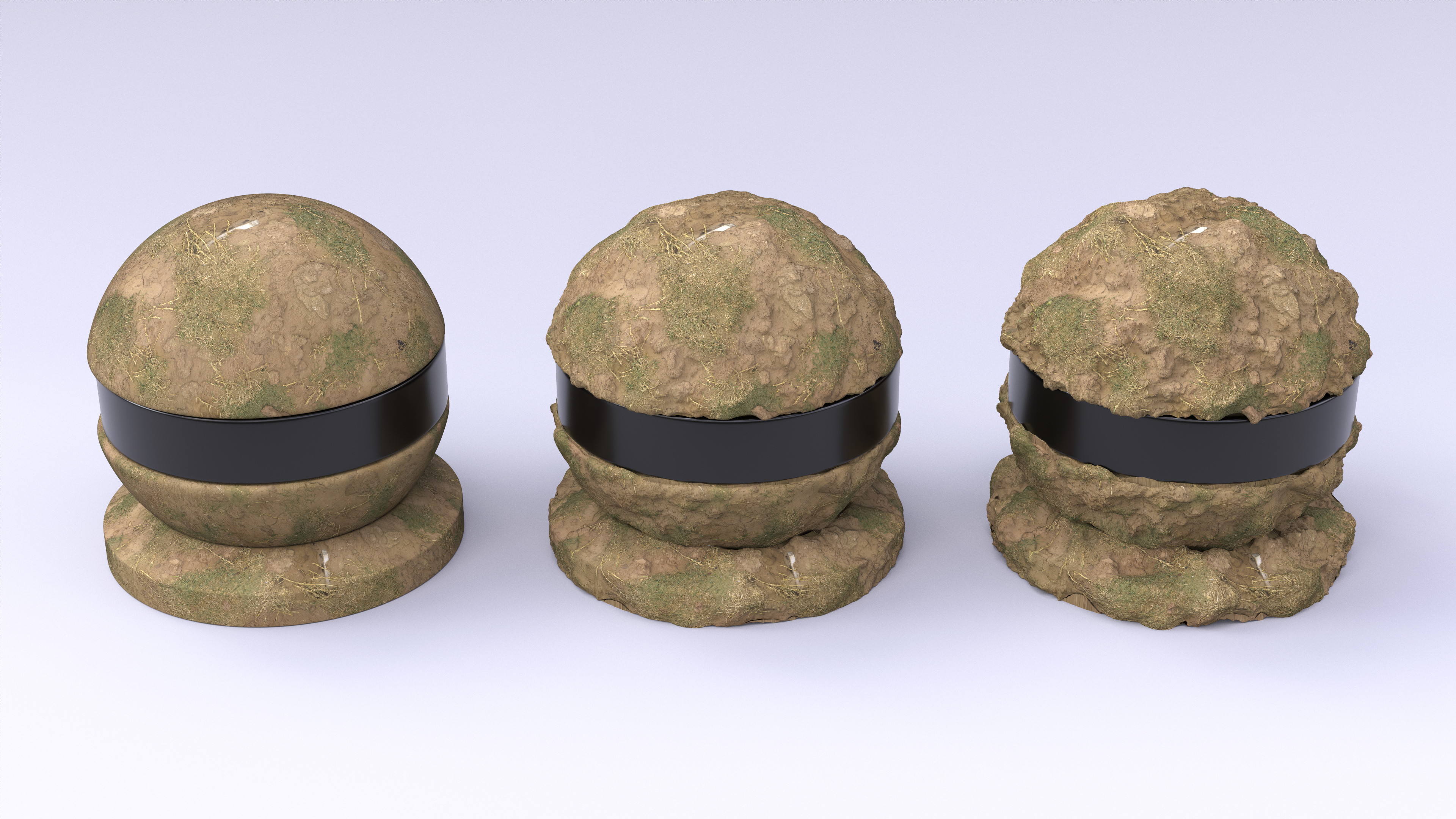
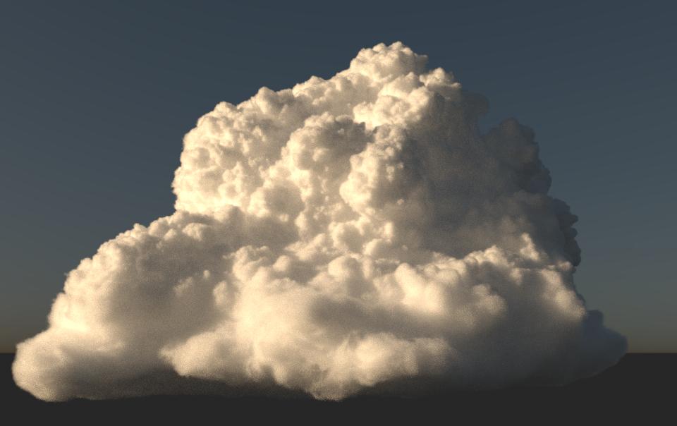
One of the major advantages of doing rendering research at a major animation or VFX studio is the availability of hundreds of extremely talented artists, who are always eager to try out new techniques and software. Peter, Ralf, and I worked closely with a number of artists at WDAS to test our techniques and produce interesting scenes with which to generate results and data for the paper. Henrik Falt and Alex Nijmeh had created a number of interesting clouds in the process of testing our general volume rendering improvements, and worked with us to adapt a cloud dataset for use in Figure 11 of our paper. The following is one of the renders from Figure 11:
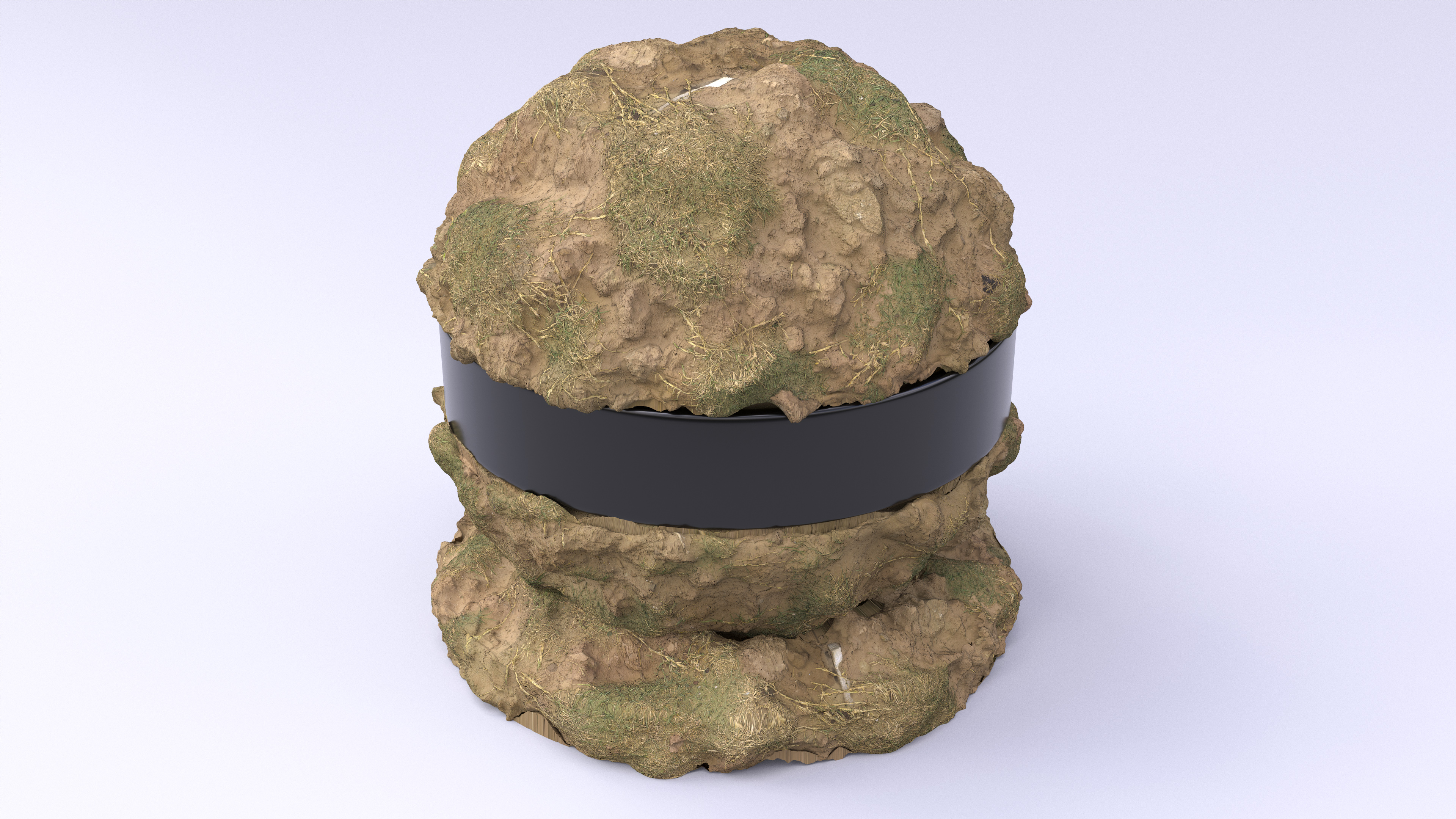
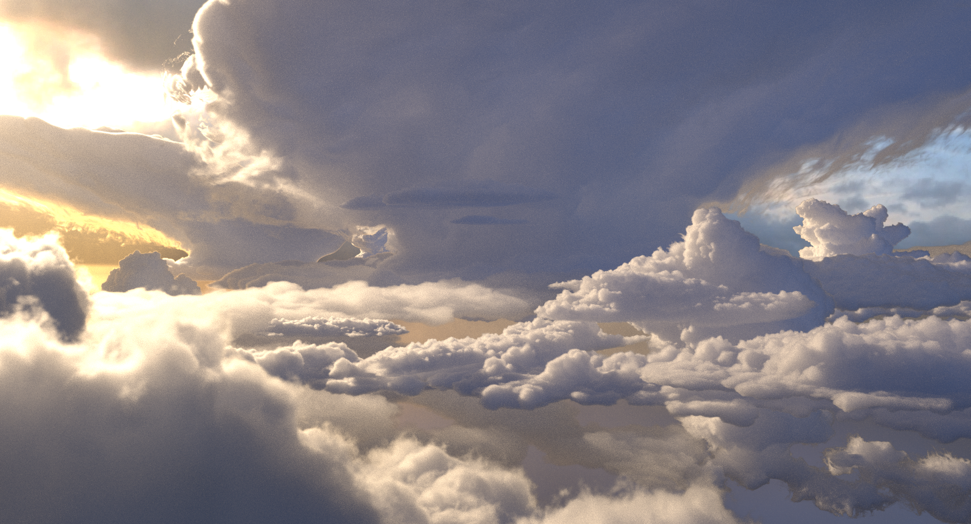
Henrik and Alex also constructed the cloudscape scene used as the banner image on the first page of the paper. After we submitted the paper, Henrik and Alex continued iterating on this scene, which eventually resulted in the more detailed version seen in our SIGGRAPH Fast Forward video. The version of the cloudscape used in our paper is reproduced below:
To test out spectral tracking, we wanted an interesting, dynamic, colorful dataset. After describing spectral tracking to Jesse Erickson, we arrived at the idea of a color explosion similar in spirit to certain visuals used in recent Apple and Microsoft ads, which in turn were inspired by the Holi festival celebrated in India and Nepal. Jesse authored the color explosion in Houdini and provided a set of VDBs for each color section, which we were then able to shade, light, and render using Hyperion’s implementation of spectral tracking. The final result was the color explosion from Figure 12 of the paper, seen at the top of this post. We were honored to learn that the color explosion figure was chosen to be one of the pictures on the back cover of this year’s conference proceedings!
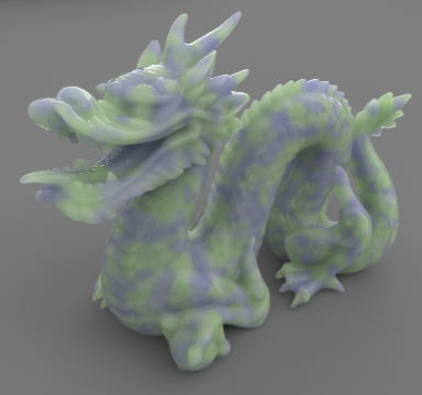
At one point we also remembered that brute force path-traced subsurface scattering is just volume rendering inside of a bounded surface, which led to the translucent heterogeneous Stanford dragon used in Figure 15 of the paper:
For our video for the SIGGRAPH 2017 Fast Forward, we were able to get a lot of help from a number of artists. Alex and Henrik and a number of other artists significantly expanded and improved the cloudscape scene, and we also rendered out several more color explosion variants. The final fast forward video contains work from Alex Nijmeh, Henrik Falt, Jesse Erickson, Thom Wickes, Michael Kaschalk, Dale Mayeda, Ben Frost, Marc Bryant, John Kosnik, Mir Ali, Vijoy Gaddipati, and Dimitre Berberov. The awesome title effect was thought up by and created by Henrik. The final video is a bit noisy since we were severely constrained on available renderfarm resources (we were basically squeezing our renders in between actual production renders), but I think the end result is still really great:
Here are a couple of cool stills from the fast forward video:


We owe an enormous amount of thanks to fellow Hyperion teammate Patrick Kelly, who played an instrumental role in designing and implementing our overall new volume rendering system, and who discussed with us extensively throughout the project. Hyperion teammate David Adler also helped out a lot in profiling and instrumenting our code. We also must thank Thomas Müller, Marios Papas, Géraldine Conti, and David Adler for proofreading, and Brent Burley, Michael Kaschalk, and Rajesh Sharma for providing support, encouragement, and resources for this project.
I’ve worked on a SIGGRAPH Asia paper before, but working on a large scale publication in the context of a major animation studio instead of in school was a very different experience. The support and resources we were given and the amount of talent and help that we were able to tap into made this project possible. This project is also an example of the incredible value that comes from companies maintaining in-house industrial research labs; this project absolutely would not have been possible without all of the collaboration from DRZ, in both the form of direct collaboration from Jan and indirect collaboration from all of the DRZ researchers that provided discussions and feedback. Everyone worked really hard, but overall the whole process was immensely intellectually satisfying and fun, and seeing our new techniques in use by talented, excited artists makes all of the work absolutely worthwhile!