Thoughts on Stackless KD-Tree Traversal
Edit: Erwin Coumans in the comments section has pointed me to a GDC 2009 talk by Takahiro Harada proposing something called Tree Traversal using History Flags, which is essentially the same as the idea proposed in this post, with the small exception that Harada’s technique uses a bit field to track previously visited nodes on the up traverse. I think that Harada’s technique is actually better than the pointer check I wrote about in this post, since keeping a bit field would allow for tracking the previously visited node without having to go back to global memory to do a node check. In other words, the bit field method allows for less thrashing of global memory, which I should think allows for a nice performance edge. So, much as I suspected, the idea in this post in one that folks smarter than me have arrived upon previously, and my knowledge of the literature on this topic is indeed incomplete. Much thanks to Erwin for pointing me to the Harada talk! The original post is preserved below, in case anyone still has an interest in reading it.
Of course, one of the biggest challenges to implementing a CUDA pathtracer is the lack of recursion on pre-Fermi GPUs. Since I intend for Takua-RT to be able to run on any CUDA enabled CPU, I necessarily have to work with the assumption that I won’t have recursion support. Getting around this problem in the core pathtracer is not actually a significant issue, as building raytracing systems that operate in an iterative fashion as opposed to in a recursive fashion is a well-covered topic.
Traversing a kd-tree without recursion, however, is a more challenging proposition. So far as I can tell from a very cursory glance at existing literature on the topic, there are presently two major approaches: fully stack-less methods that require some amount of pre-processing of the kd-tree, such as the rope-based method presented in Popov et. al. [2007], and methods utilizing a short stack or something similar, such as the method presented in Zhou et. al. [2008]. I’m in the process of reading both of these papers more carefully, and will probably explore at least one of these approaches soon. In the meantime, however, I thought it might be a fun exercise to try to come up with some solution of my own, which I’ll summarize in this post. I have to admit that I have no idea if this is actually a novel approach, or if its something that somebody also came up with and rejected a long time ago and I just haven’t found yet. My coverage of the literature in this area is highly incomplete, so if you, the reader, are aware of a pre-existing version of this idea, please let me know so that I can attribute it properly!
The basic idea I’m starting with is that when traversing a KD-tree (or any other type of tree, for that matter), at a given node, there’s only a finite number of directions one can go in, and a finite number of previous nodes one could have arrived at the current node from. In other words, one could conceivably define a finite-state machine type system for traversing a KD-tree, given an input ray. I say finite-state machine type, because what I shall define here isn’t actually strictly a FSM, as this method requires storing information about the previous state in addition to the current state. So here we go:
We begin by tracking two pieces of information: what the current node we are at is, and what direction we had to take from the previous node to get to the current node. There are three possible directions we could have come from:
- Down from the current node’s parent node
- Up from the current node’s left child
- Up from the current node’s right child
Similarly, there are only three directions we can possibly travel in from the current node:
- Up to the current node’s parent node
- Down to the current node’s left child
- Down to the current node’s right child
When we travel up from the current node to its parent, we can easily figure out if we are traveling up from the right or the left by looking at whether the current node is the parent node’s left or right child.
Now we need a few rules on which direction to travel in given the direction we came from and some information on where our ray currently is in space:
- If we came down from the parent node and if the current node is not a leaf node, intersection test our ray with both children of the current node. If the ray only intersects one of the children, traverse down to that child. If the ray intersects both of the children, traverse down to the left child.
- If we came down from the parent node and if the current node is a leaf node, carry out intersection tests between the ray and the contents of the node and store the nearest intersection.
- If we came up from the left child, intersection test our ray with the right child of the current node. If we have an intersection, traverse down the right child. If we don’t have an intersection, traverse upwards to the parent.
- If we came up from the right child, traverse upwards to the parent.
That’s it. With those four rules, we can traverse an entire KD-Tree in a DFS fashion, while skipping branches that our ray does not intersect for a more efficient traverse, and avoiding any use of recursion or the use of a stack in memory.
There is, of course, the edge case that our ray is coming in to the tree from the “back”, so that the right child of each node is “in front” of the left child instead of “behind”, but we can easily deal with this case by simply testing which side of the KD-tree we’re entering from and swapping left and right in our ruleset accordingly.
I haven’t actually gotten around to implementing this idea yet (as of September 15th, when I started writing this post, although this post may get published much later), so I’m not sure what the performance looks like. There are some inefficiencies in how many nodes our traverse will end up visiting, but on the flipside, we won’t need to keep much of anything in memory except for two pieces of state information and the actual KD-tree itself. On the GPU, I might run into implementation level problems that could impact performance, such as too many branching statements or memory thrashing if the KD-tree is kept in global memory and a gazillion threads try to traverse it at once, so these issues will need to be addressed later.
Again, if you, the reader, knows of this idea from a pre-existing place, please let me know! Also, if you see a gaping hole in my logic, please let me know too!
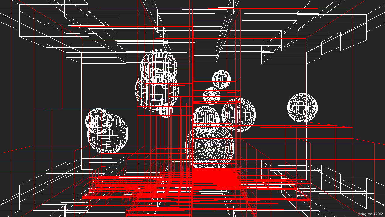
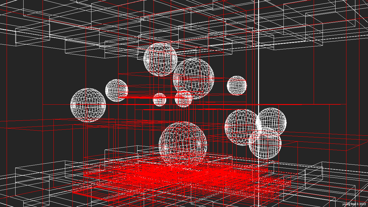
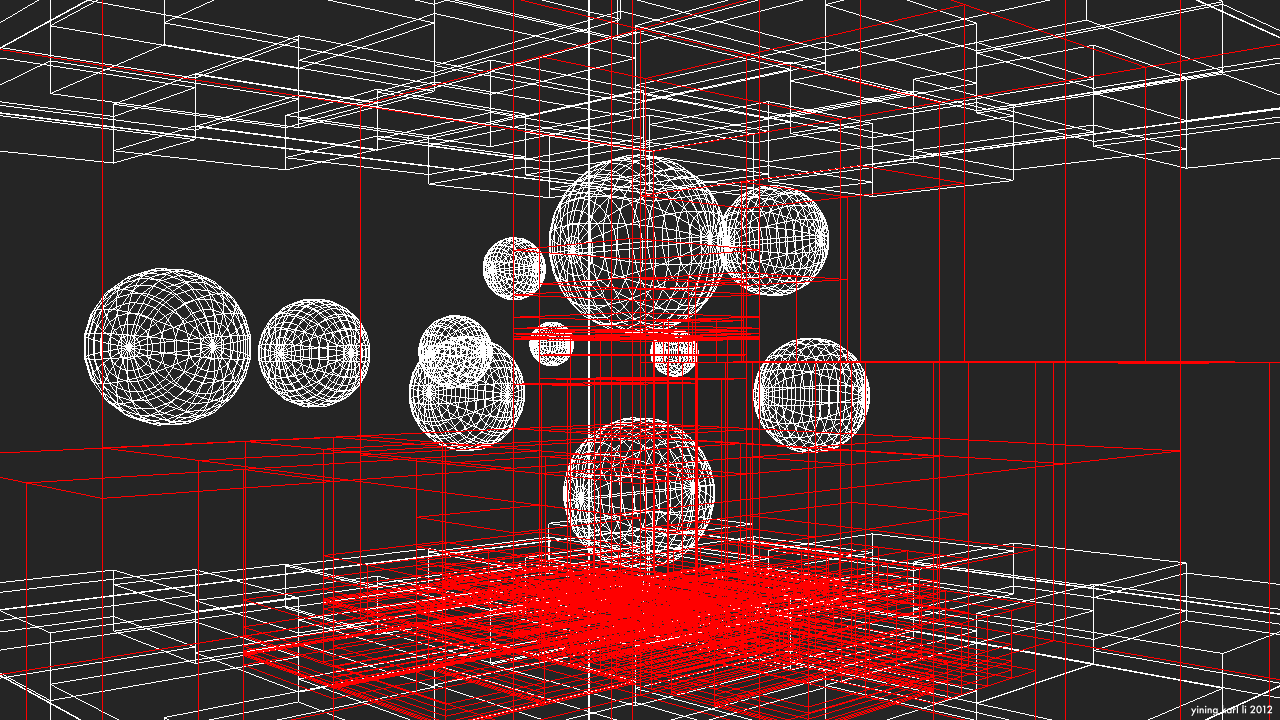
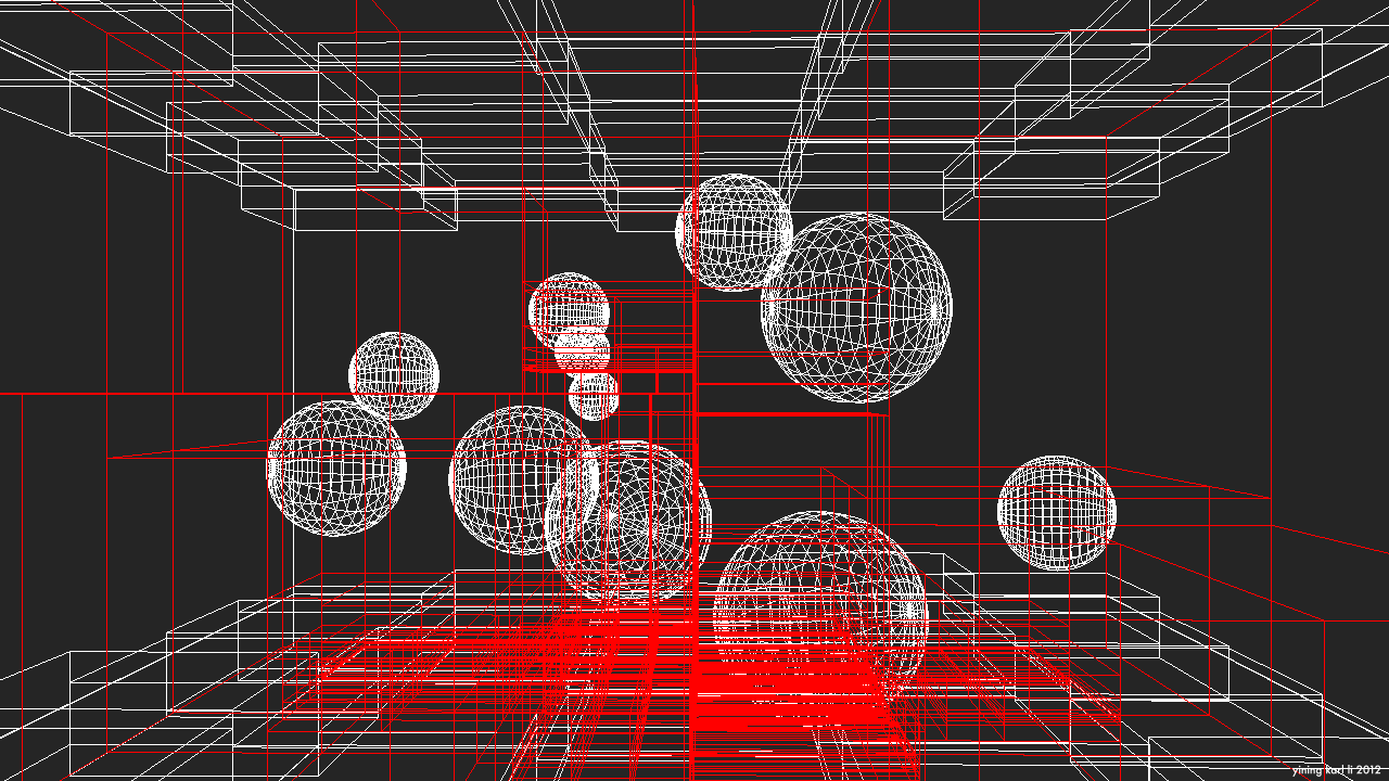
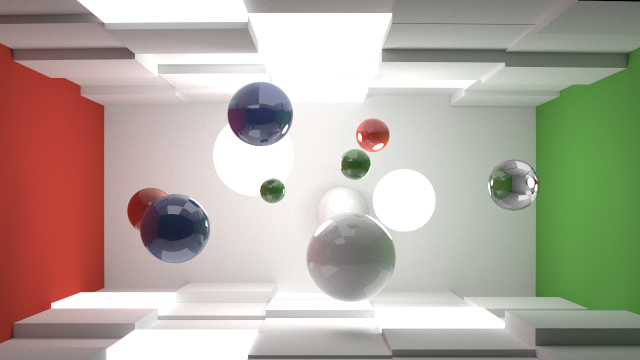
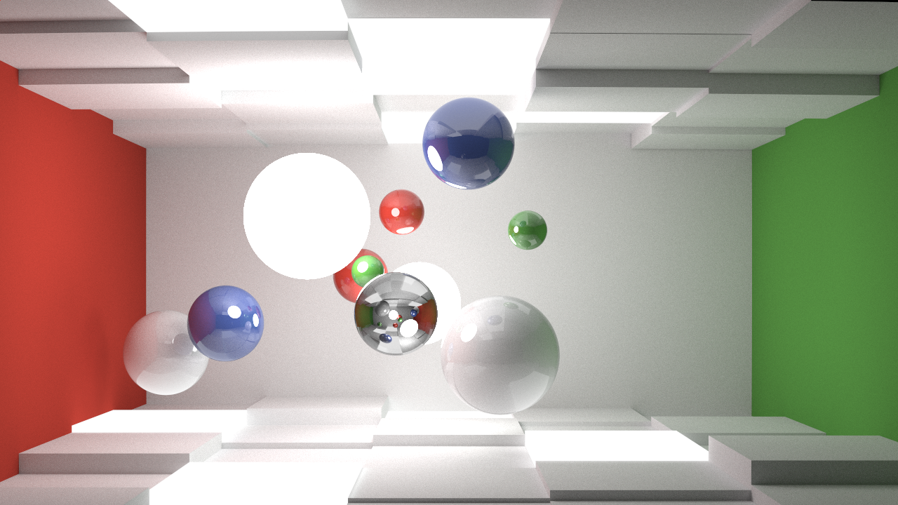
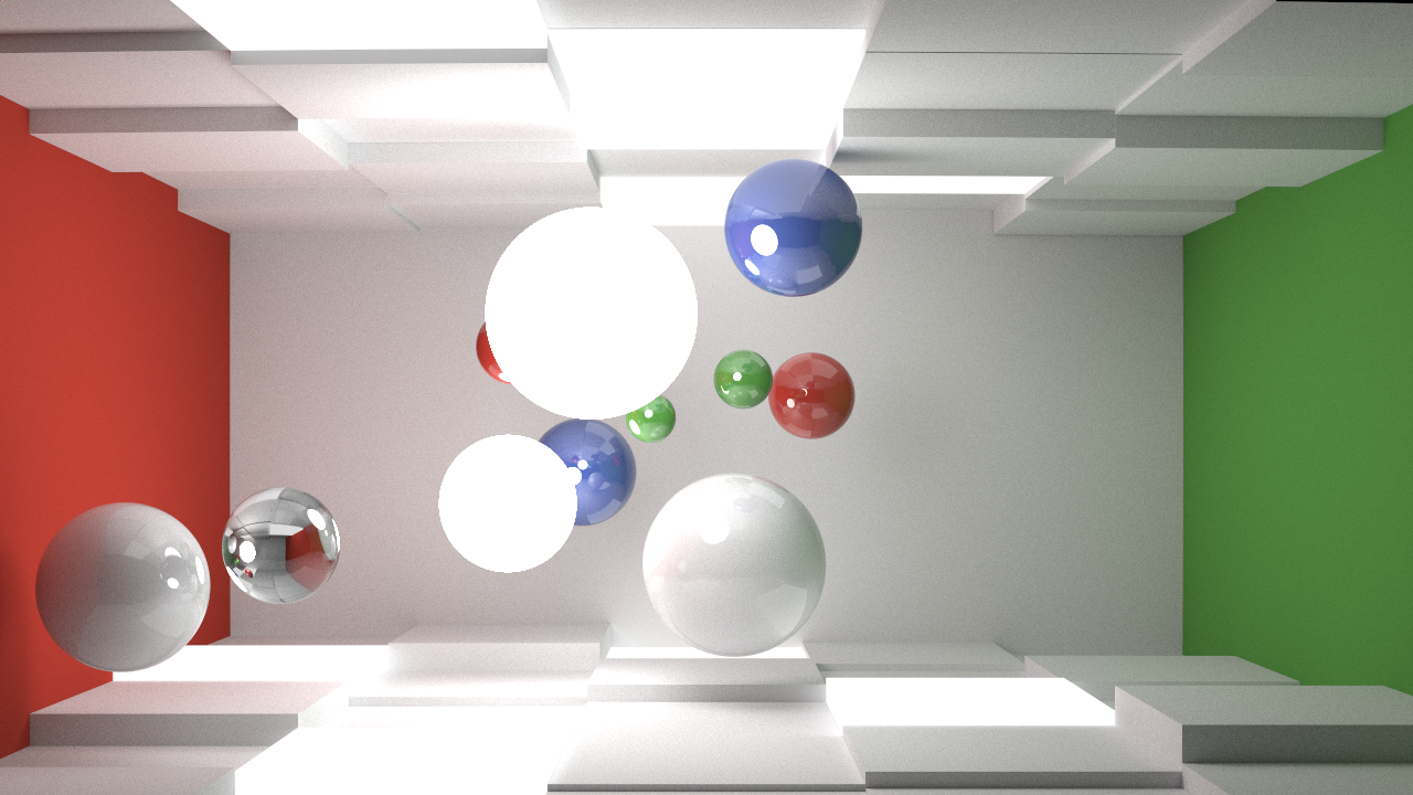
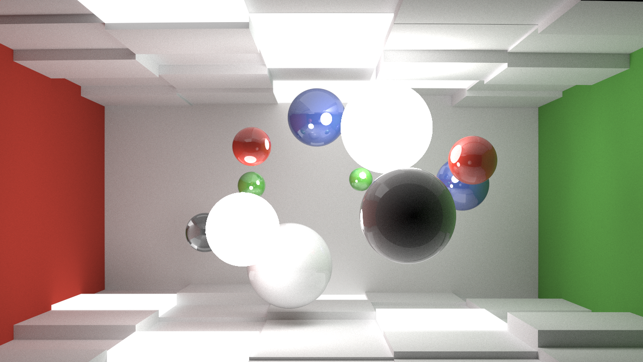
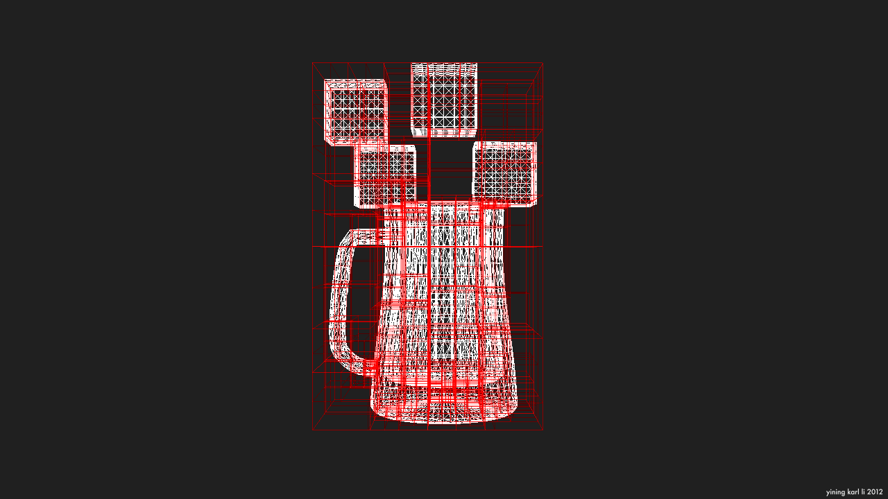
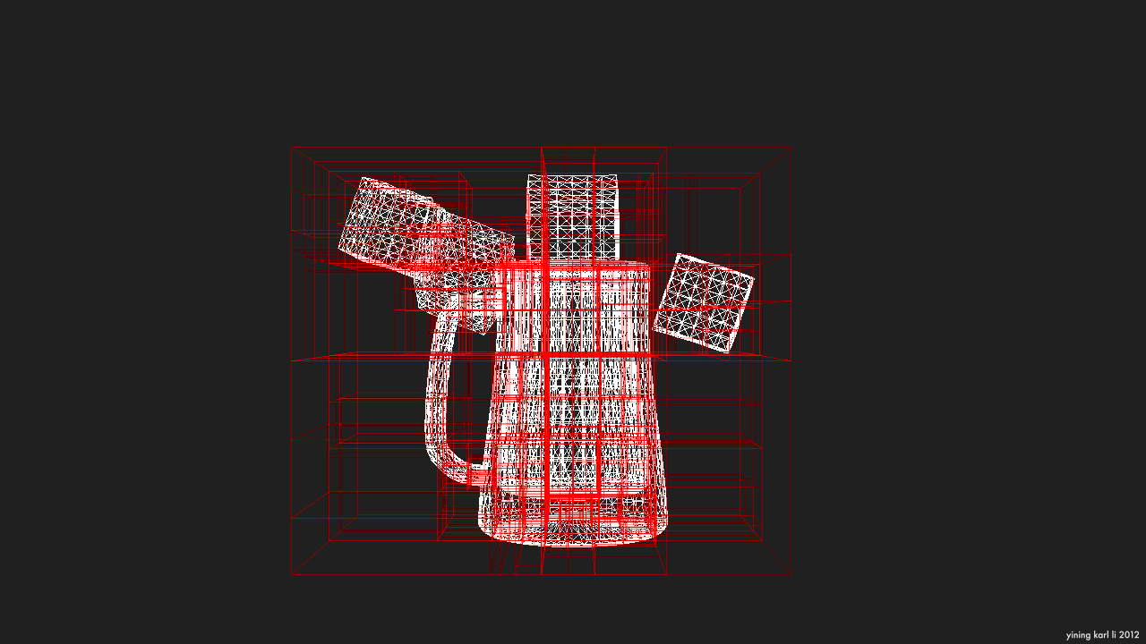
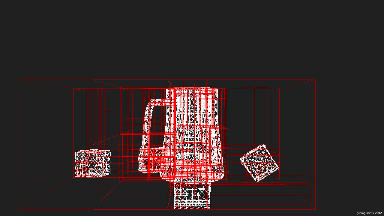
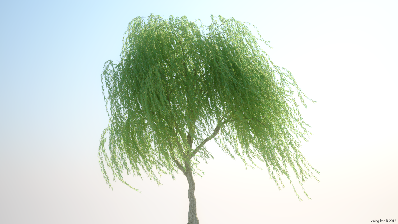
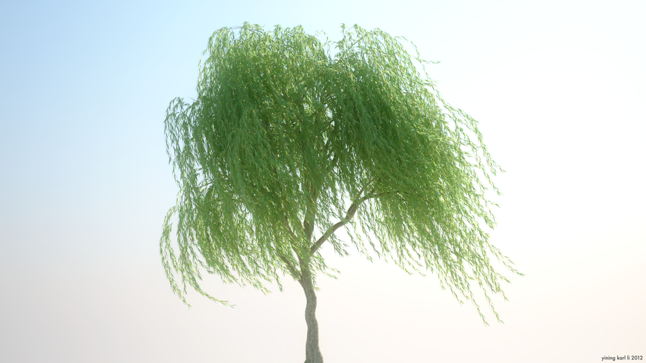
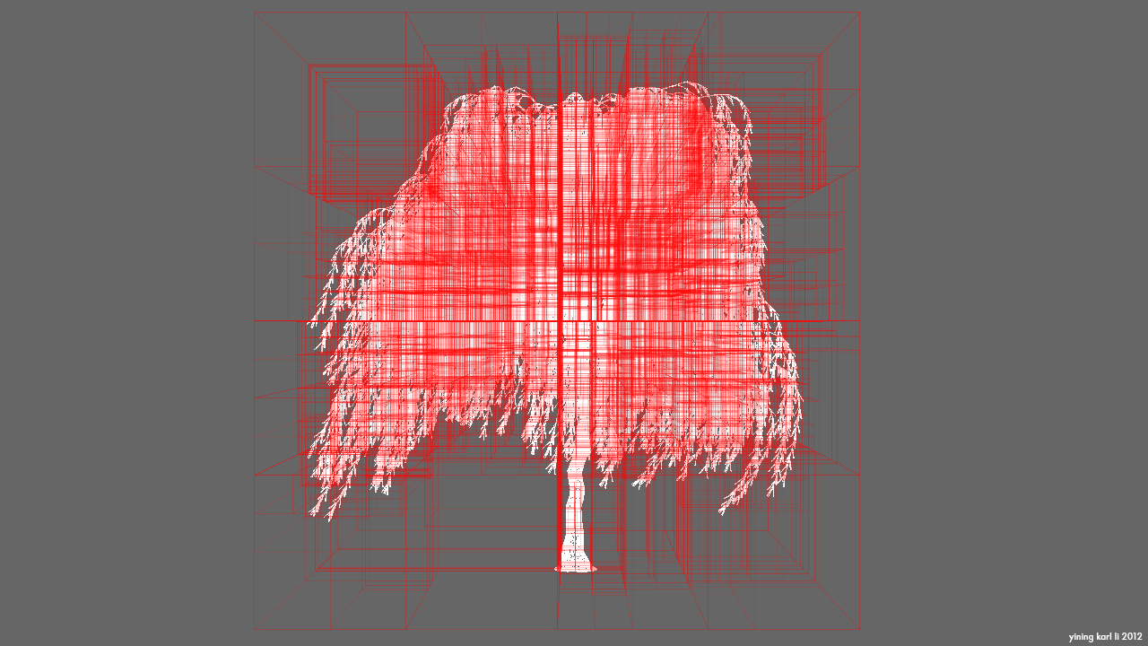
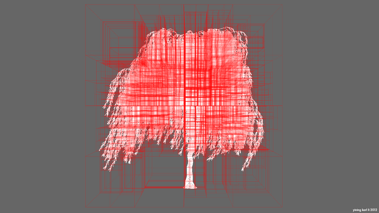
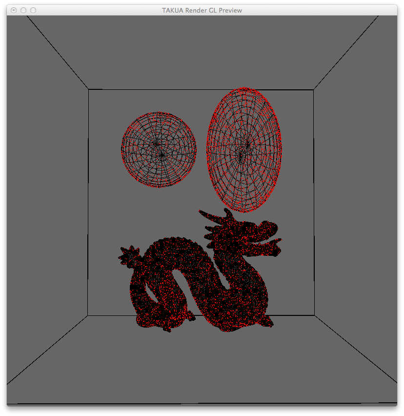
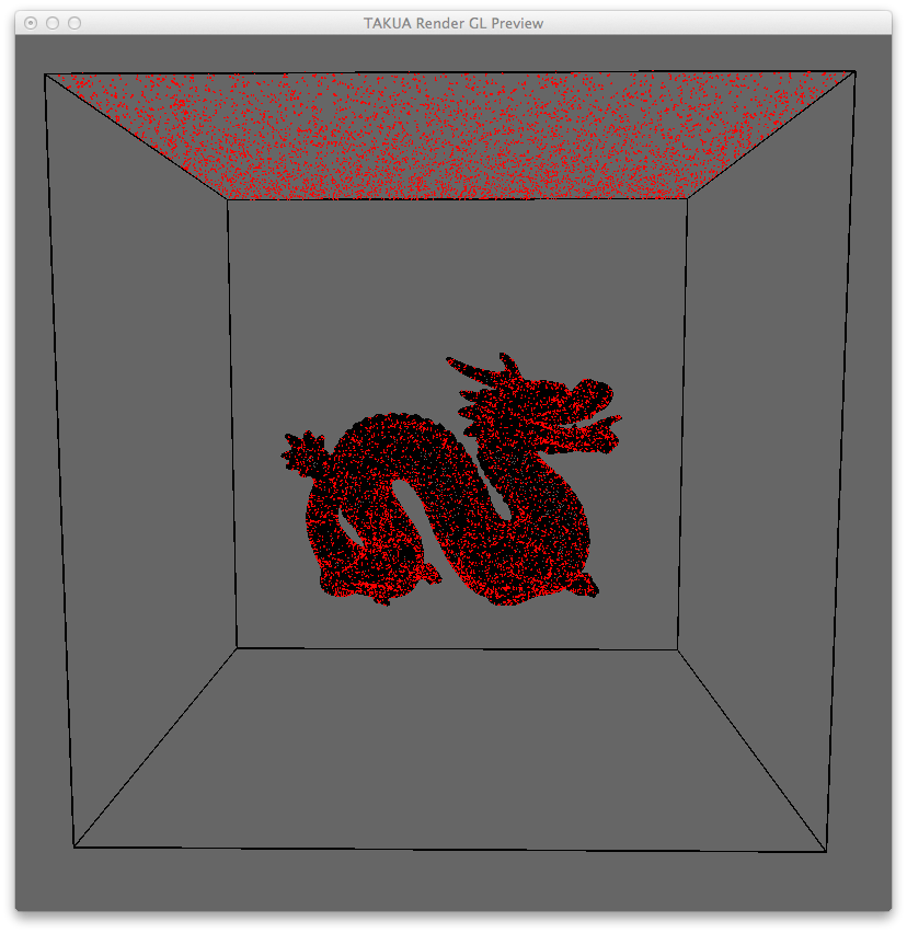
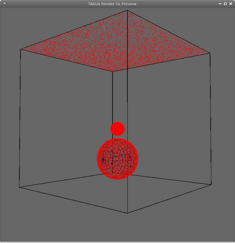
Since this has been a very text heavy post, I’ll close with some pictures of a KD-tree representing the scene from the Takua-RT post. They don’t really have much to do with the traverse method presented in this post, but they are KD-tree related!
Vimeo’s compression really does not like thin narrow lines, so here are some stills:
