Nested Dielectrics
Table of Contents
Introduction
A few years ago, I wrote a post about attenuated transmission and what I called “deep attenuation” at the time- refraction and transmission through multiple mediums embedded inside of each other, a.k.a. what is usually called nested dielectrics. What I called “deep attenuation” in that post is, in its essence, just pure interface tracking using a stack. This post is meant as a revisit and update of that post; I’ll talk about the problems with the ad-hoc pure interface tracking technique I came up with in that previous post and discuss the proper priority-based nested dielectric technique [Schmidt and Budge 2002] that Takua uses today.
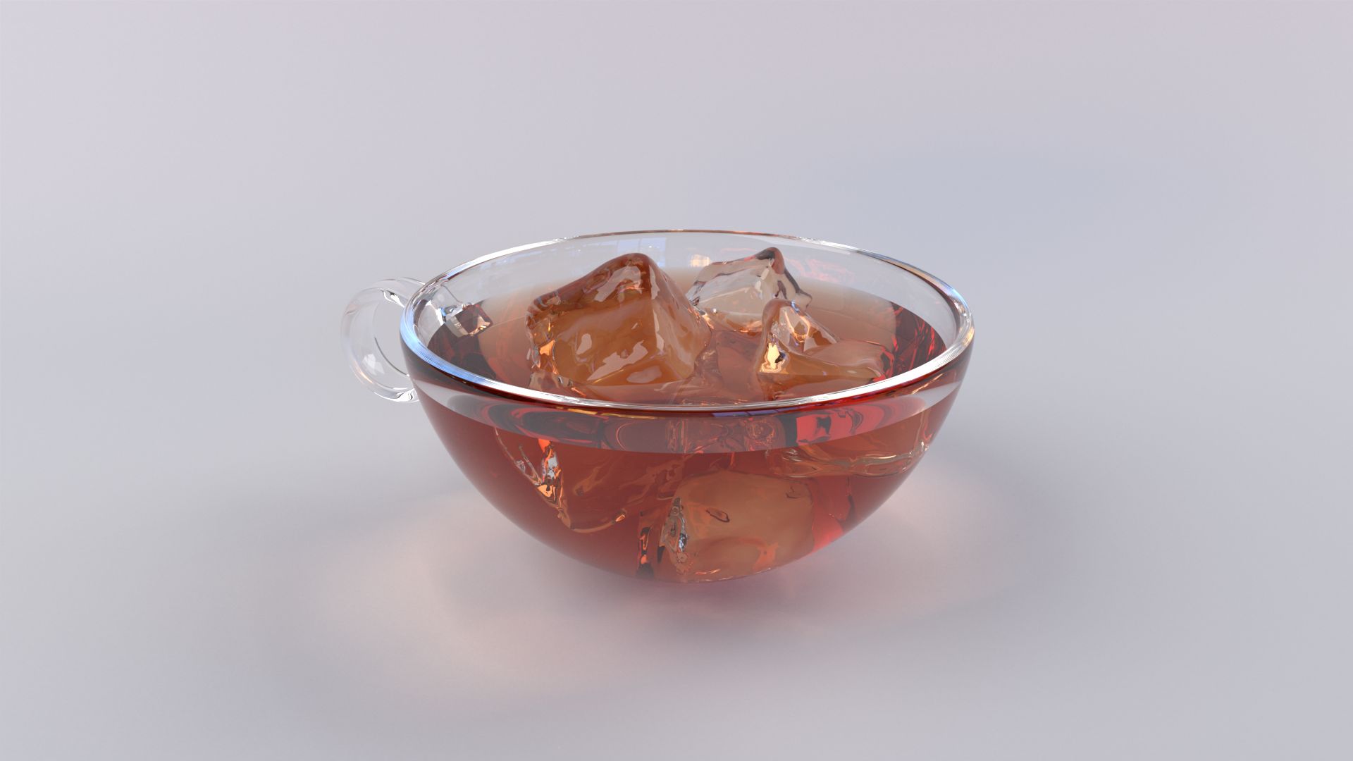
In my 2015 post, I included a diagram showing the overlapping boundaries required to model ice cubes in a drink in a glass, but I didn’t actually include a render of that scenario! In retrospect, the problems with the 2015 post would have become obvious to me more quickly if I had actually done a render like that diagram. Figure 1 shows an actual “ice cubes in a drink in a glass” scene, rendered correctly using Takua Renderer’s implementation of priority-based nested dielectrics. For comparison, Figure 2 shows what Takua produces using the approach in the 2015 post; there are a number of obvious bizarre problems! In Figure 2, the ice cubes don’t properly refract the tea behind and underneath them, and the ice cubes under the liquid surface aren’t visible at all. Also, where the surface of the tea interfaces with the glass teacup, there is a odd bright ring. Conversely, Figure 1 shows a correct liquid-glass interface without a bright ring, shows proper refraction through the ice cubes, and correctly shows the ice cubes under the liquid surface.

Problems with only Interface Tracking
So what exactly is wrong with using only interface tracking without priorities? First, let’s quickly summarize how my old interface tracking implementation worked. Note that here we refer to the side of a surface a ray is currently on as the incident side, and the other side of the surface as the transmit side. For each path, keep a stack of which Bsdfs the path has encountered:
- When a ray enters a surface, push the encountered surface onto the stack.
- When a ray exits a surface, scan the stack from the top down and pop the first instance of a surface in the stack matching the encountered surface.
- When hitting the front side of a surface, the incident properties comes from the top of the stack (or is the empty default if the stack is empty), and the transmit properties comes from surface being intersected.
- When hitting the back side of a surface, the incident properties comes from the surface being intersected, and the transmit properties comes from the top of the stack (or is the empty default if the stack is empty).
- Only push/pop onto the stack when a refraction/transmission event occurs.
Next, as an example, imagine a case where which surface a ray currently in is ambiguous. A common example of this case is when two surfaces are modeled as being slightly overlapping, as is often done when modeling liquid inside of a glass since modeling perfectly coincident surfaces in CG is either extremely difficult or impossible due to floating point precision problems. Even if we could model perfectly coincident surfaces, rendering perfectly coincident surfaces without artifacts is similarly extremely difficult or impossible, also due to floating point precision problems. Figure 3 shows a diagram of how a glass containing water and ice cubes is commonly modeled; in Figure 3, the ambiguous regions are where the water surface is inside of the glass and inside of the ice cube. When a ray enters this overlapping region, it is not clear whether we should treat the ray as being inside the water or inside if the glass (or ice)!
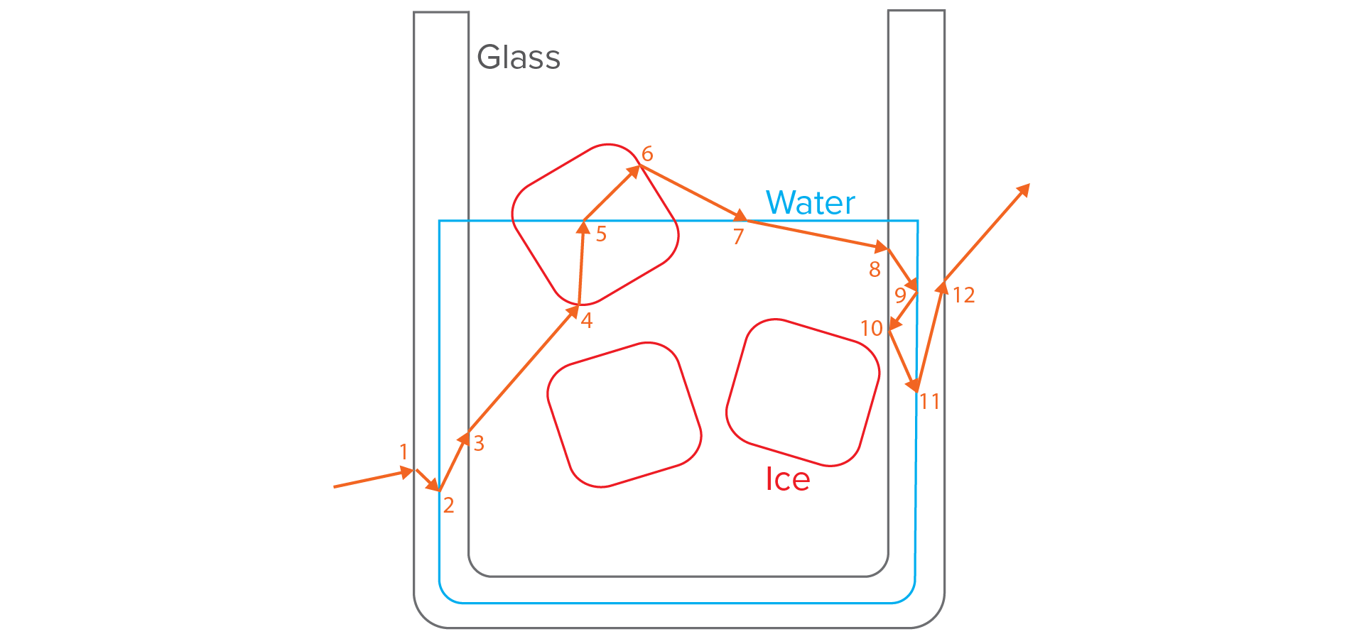
Using the pure interface tracking algorithm from my old blog post, below is what happens at each path vertex along the path illustrated in Figure 3. In this example, we define the empty default to be air.
- Enter Glass.
- Incident/transmit IOR: Air/Glass.
- Push Glass onto stack. Stack after event: (Glass).
- Enter Water.
- Incident/transmit IOR: Glass/Water.
- Push Water onto stack. Stack after event: (Water, Glass).
- Exit Glass.
- Incident/transmit IOR: Glass/Water.
- Remove Glass from stack. Stack: (Water).
- Enter Ice.
- Incident/transmit IOR: Water/Ice.
- Push Ice onto stack. Stack: (Ice, Water).
- Exit Water.
- Incident/transmit IOR: Water/Ice.
- Remove Water from stack. Stack: (Ice).
- Exit Ice.
- Incident/transmit IOR: Ice/Air.
- Remove Ice from stack. Stack: empty.
- Enter Water.
- Incident/transmit IOR: Air/Water.
- Push Water onto stack. Stack after event: (Water).
- Enter Glass.
- Incident/transmit IOR: Water/Glass.
- Push Glass onto stack. Stack after event: (Glass, Water).
- Reflect off Water.
- Incident/transmit IOR: Water/Glass.
- No change to stack. Stack after event: (Glass, Water).
- Reflect off Glass.
- Incident/transmit IOR: Glass/Glass.
- No change to stack. Stack after event: (Glass, Water).
- Exit Water.
- Incident/transmit IOR: Water/Glass.
- Remove Water from stack. Stack after event: (Glass).
- Exit Glass.
- Incident/transmit IOR: Glass/Air.
- Remove Glass from stack. Stack after event: empty.
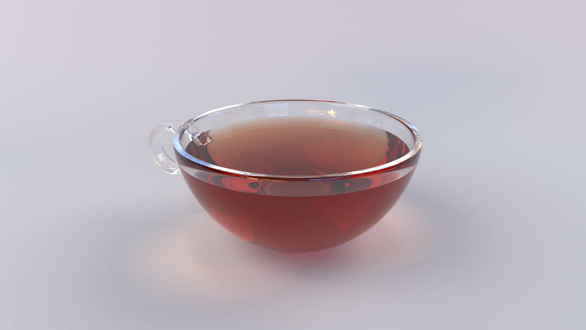
Observe events 3 and 5, where the same index of refraction boundary is encountered as in the previous event. These double events are where some of the weirdness in Figure 2 comes from; specifically the bright ring at the liquid-glass surface interface and the incorrect refraction through the ice cube. These double events are not actually physically meaningful; in reality, a ray could never be both inside of a glass surface and inside of a water surface simultaneously. Figure 4 shows a simplified version of the tea cup example above, without ice cubes; even then, the double event still causes a bright ring at the liquid-glass surface interface. Also note how when following the rules from my old blog post, event 10 becomes a nonsense event where the incident and transmit IOR are the same. The fix for this case is to modify the rules so that when a ray exits a surface, the transmit properties come from the first surface on the stack that isn’t the same as the incident surface, but even with this fix, the reflection at event 10 is still physically impossible.

Really what we want is to model overlapping surfaces, but then in overlapping areas, be able to specify which surface a ray should think it is actually inside of. Essentially, this functionality would make overlapping surfaces behave like boolean operators; we would be able to specify that the ice cubes in Figure 3 “cut out” a space from the water they overlap with, and the glass cut out a space from the water as well. This way, the double events never occur since rays wouldn’t see the second event in each pair of double events. One solution that immediately comes to mind is to simply consider whatever surface is at the top of the interface tracking stack as being the surface we are currently inside, but this causes an even worse problem: the order of surfaces that a ray thinks it is in becomes dependent on what surfaces a ray encounters first, which depends on the direction and location of each ray! This produces an inconsistent view of the world across different rays. Instead, a better solution is provided by priority-based nested dielectrics [Schmidt and Budge 2002].
Priority-Based Nested Dielectrics
Priority-based nested dielectrics work by assigning priority values to geometry, with the priority values determining which piece of geometry “wins” when a ray is in a region of space where multiple pieces of geometry overlap. A priority value is just a single number assigned as an attribute to a piece of geometry or to a shader; the convention established by the paper is that lower numbers indicate higher priority. The basic algorithm in [Schmidt and Budge 2002] works using an interior list, which is conceptually similar to an interface tracking stack. The interior list is exactly what it sounds like: a list of all of the surfaces that a path has entered but not exited yet. Unlike the interface tracking stack though, the interior list doesn’t necessarily have to be a stack or have any particular ordering, although implementing it as a list always sorted by priority may provide some minor practical advantages. When a ray hits a surface during traversal, the following rules apply:
- If the surface has a higher or equal priority (so lower or equal priority number) than anything else on the interior list, the result is a true hit and a intersection has occured. Proceed with regular shading and Bsdf evaluation.
- If the surface has a lower priority (so higher priority number) than the highest-priority value on the interior list, the result is a false hit and no intersection has occured. Ignore the intersection and continue with ray traversal.
- If the hit is a false hit OR if the hit both is a true hit and results in a refraction/transmission event:
- Add the surface to the interior list if the ray is entering the surface.
- Remove the surface from the interior list if the ray is exiting the surface.
- For a true hit the produces a reflection event, don’t add the surface to the interior list.
Note that this approach only works with surfaces that are enclosed manifolds; that is, every surface defines a finite volume. When a ray exits a surface, the surface it is exiting must already be in the interior list; if not, then the interior list can become corrupted and the renderer may start thinking that paths are in surfaces that they are not actually in (or vice verse). Also note that a ray can only ever enter into a higher-priority surface through finding a true hit, and can only enter into a lower-priority surface by exiting a higher-priority surface and removing the higher-priority surface from the interior list. At each true hit, we can figure out the properties of the incident and transmit sides by examining the interior list. If hitting the front side of a surface, before we update the interior list, the surface we just hit provides the transmit properties and the highest-priority surface on the interior list provides the incident properties. If hitting the back side of a surface, before we update the interior list, the surface we just hit provides the incident properties and the second-highest-priority surface on the interior list provides the transmit properties. Alternatively, if the interior list only contains one surface, then the transmit properties come from the empty default. Importantly, if a ray hits a surface with no priority value set, that surface should always count as a true hit. This way, we can embed non-transmissive objects inside of transmissive objects and have everything work automatically.
Figure 5 shows the same scenario as in Figure 3, but now with priority values assigned to each piece of geometry. The path depicted in Figure 5 uses the priority-based interior list; dotted lines indicate parts of a surface that produce false hits due to being embedded within a higher-priority surface:
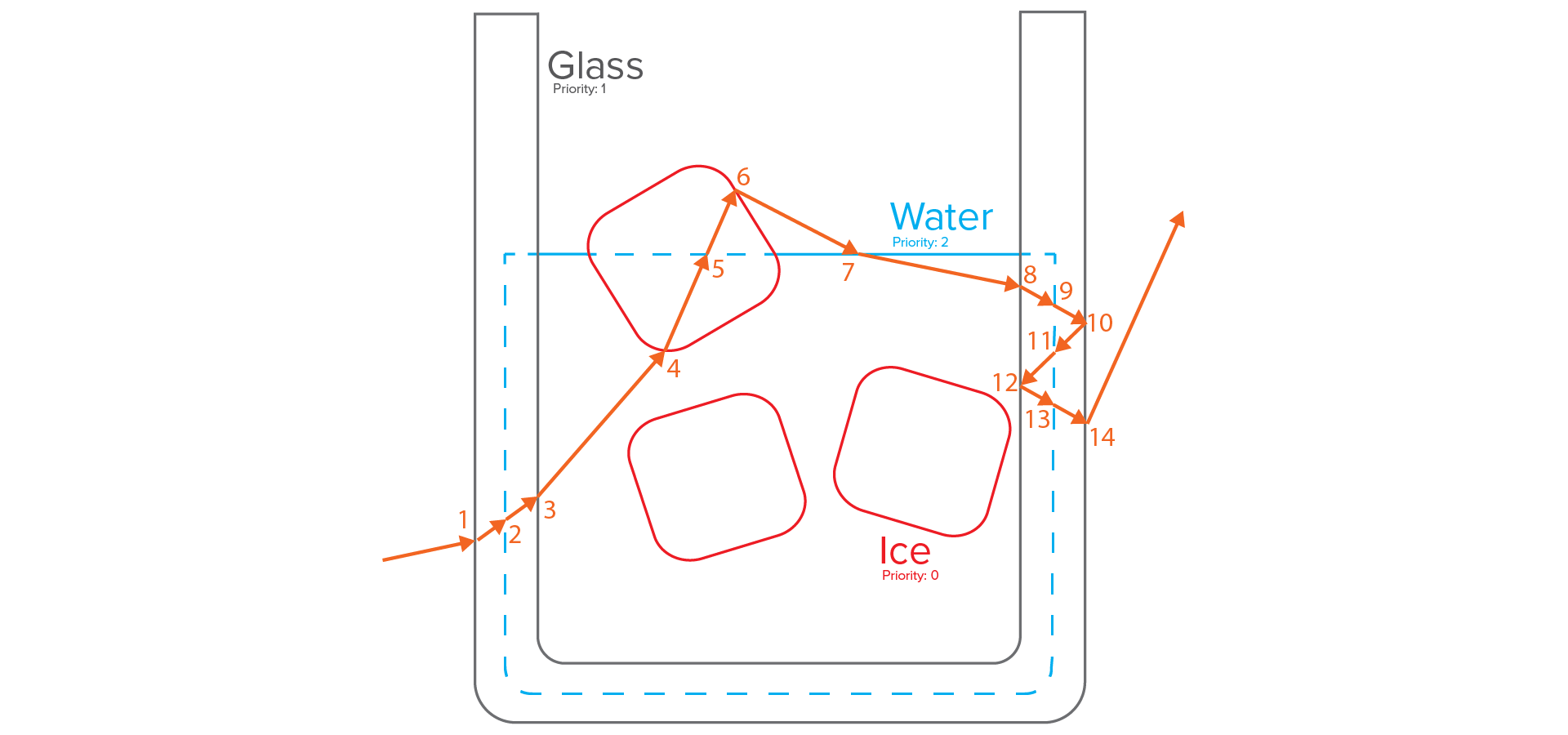
The empty default air surrounding everything is defined as having an infinitely high priority value, which means a lower priority than any surface in the scene. Using the priority-based interior list, here are the events that occur at each intersection along the path in Figure 5:
- Enter Glass.
- Glass priority (1) is higher than ambient air (infinite), so TRUE hit.
- Incident/transmit IOR: Air/Glass.
- True hit, so evaluate Bsdf and produce refraction event.
- Interior list after event: (Glass:1). Inside surface after event: Glass.
- Enter Water.
- Water priority (2) is lower than highest priority in interior list (1), so FALSE hit.
- Incident/transmit IOR: N/A.
- False hit, so do not evaluate Bsdf and just continue straight.
- Interior list after event: (Glass:1, Water:2). Inside surface after event: Glass.
- Exit Glass.
- Glass priority (1) is equal to the highest priority in interior list (1), so TRUE hit.
- Incident/transmit IOR: Glass/Water.
- True hit, so evaluate Bsdf and produce refraction event. Remove Glass from interior list.
- Interior list after event: (Water:2). Inside surface after event: Water.
- Enter Ice.
- Ice priority (0) is higher than the highest priority in interior list (2), so TRUE hit.
- Incident/transmit IOR: Water/Ice.
- True hit, so evaluate Bsdf and produce refraction event.
- Interior list after event: (Water:2, Ice:0). Inside surface after event: Ice.
- Exit Water.
- Ice priority (0) is higher than the highest priority in interior list (2), so TRUE hit.
- Incident/transmit IOR: N/A.
- False hit, so do not evaluate Bsdf and just continue straight. Remove Water from interior list.
- Interior list after event: (Ice:0). Inside surface after event: Ice.
- Exit Ice.
- Ice priority is only surface in the interior list, so TRUE hit.
- Incident/transmit IOR: Ice/Air.
- True hit, so evaluate Bsdf and produce refraction event. Remove Ice from interior list.
- Interior list after event: empty. Inside surface after event: air.
- Enter Water.
- Water priority (2) is higher than ambient air (infinite), so TRUE hit.
- Incident/transmit IOR: Air/Water.
- True hit, so evaluate Bsdf and produce refraction event.
- Interior list after event: (Water:2). Inside surface after event: Water.
- Enter Glass.
- Glass priority (1) is higher than the highest priority in interior list (2), so TRUE hit.
- Incident/transmit IOR: Water/Glass.
- True hit, so evaluate Bsdf and produce refraction event.
- Interior list after event: (Water:2, Glass:1). Inside surface after event: Glass.
- Exit Water.
- Water priority (2) is lower than highest priority in interior list (1), so FALSE hit.
- Incident/transmit IOR: N/A.
- False hit, so do not evaluate Bsdf and just continue straight.
- Interior list after event: (Glass:1). Inside surface after event: Glass.
- Reflect off Glass.
- Glass priority (1) is equal to the highest priority in interior list (1), so TRUE hit.
- Incident/transmit IOR: Glass/Air.
- True hit, so evaluate Bsdf and produce reflection event.
- Interior list after event: (Glass:1). Inside surface after event: Glass.
- Enter Water.
- Water priority (2) is lower than highest priority in interior list (1), so FALSE hit.
- Incident/transmit IOR: N/A.
- False hit, so do not evaluate Bsdf and just continue straight.
- Interior list after event: (Glass:1, Water:2). Inside surface after event: Glass.
- Reflect off Glass.
- Glass priority (1) is equal to the highest priority in interior list (1), so TRUE hit.
- Incident/transmit IOR: Glass/Water.
- True hit, so evaluate Bsdf and produce reflection event.
- Interior list after event: (Glass:1, Water:2). Inside surface after event: Glass.
- Exit Water.
- Water priority (2) is lower than highest priority in interior list (1), so FALSE hit.
- Incident/transmit IOR: N/A.
- False hit, so do not evaluate Bsdf and just continue straight.
- Interior list after event: (Glass:1). Inside surface after event: Glass.
- Exit Glass.
- Glass priority (1) is equal to the highest priority in interior list (1), so TRUE hit.
- Incident/transmit IOR: Glass/Air.
- True hit, so evaluate Bsdf and produce refraction event. Remove Glass from interior list.
- Interior list after event: empty. Inside surface after event: air.
The entire above sequence of events is physically plausible, and produces no weird double-events! Using priority-based nested dielectrics, Takua generates the correct images in Figure 1 and Figure 6. Note how in Figure 6 below, the liquid appears to come right up against the glass, without any bright boundary artifacts or anything else.
For actually implementing priorty-based nested dielectrics in a ray tracing renderer, I think there are two equally plausible places in the renderer where the implementation can take place. The first and most obvious location is as part of standard light transport integration or shading system. The integrator would be in charge of checking for false hits and tracing continuation rays through false hit geometry. A second, slightly less obvious location is actually as part of ray traversal through the scene itself. Including handling of false hits in the traversal system can be more efficient than handling it in the integrator since the false hit checks could be done in the middle of a single BVH tree traversal, whereas handling false hits by firing continuation rays requires a new BVH tree traversal for each false hit encountered. Also, handling false hits in the traversal system removes some complexity from the integrator. However, the downside to handling false hits in the traversal system is that it requires plumbing all of the interior list data and logic into the traversal system, which sets up something of a weird backwards dependency between the traversal and shading/integration systems. I wound up choosing to implement priority-based nested dielectrics in the integration system in Takua, simply to avoid having to do complex, weird plumbing back into the traversal system. Takua uses priority-based nested dielectrics in all integrators, including unidirectional path tracing, BDPT, PPM, and VCM, and also uses the nested dielectrics system to handle transmittance along bidirectional connections through attenuating mediums.
Even though the technique has “nested dielectrics” in the title, this technique is not in principle limited to only dielectrics. In Takua, I now use this technique to handle all transmissive cases, including for both dielectric surfaces and for surfaces with diffuse transmission. Also, in addition to just determining the incident and transmit IORs, Takua uses this system to also determine things like what kind of participating medium a ray is currently inside of in order to calculate attenuation. This technique appears to be more or less the industry standard today; implementations are available for at least Renderman, Arnold, Mantra, and Maxwell Render.
As a side note, during the course of this work, I also upgraded Takua’s attenuation system to use ratio tracking [Novák et al. 2014] instead of ray marching when doing volumetric lookups. This change results in an important improvement to the attenuation system: ratio tracking provides an unbiased estimate of transmittance, whereas ray marching is inherently biased due to being a quadrature-based technique.
Figures 7 and 8 show a fancier scene of liquid pouring into a glass with some ice cubes and such. This scene is the Glass of Water scene from Benedikt Bitterli’s rendering resources page [Bitterli 2016], modified with brighter lighting on a white backdrop and with red liquid. I also had to modify the scene so that the liquid overlaps the glass slightly; providing a clearer read for the liquid-glass interface is why I made the liquid red. One of the neat features of this scene are the cracks modeled inside of the ice cubes; the cracks are non-manifold geometry. To render them correctly, I applied a shader with glossy refraction to the crack geometry but did not set a priority value for them; this works correctly because the cracks, being non-manifold, don’t have a concept of inside or outside anyway, so they should not participate in any interior list considerations.


References
Benedikt Bitterli. 2016. Rendering Resources. Retrieved from https://benedikt-bitterli.me/resources/.
Jan Novák, Andrew Selle and Wojciech Jarosz. 2014. Residual Ratio Tracking for Estimating Attenuation in Participating Media. ACM Transactions on Graphics (Proc. of SIGGRAPH Asia) 33, 6 (Nov. 2014), Article 179.
Charles M. Schmidt and Brian Budge. 2002. Simple Nested Dielectrics in Ray Traced Images. Journal of Graphics Tools 7, 2 (Jan. 2002), 1–8.
Some Blog Update Notes
For the past few years, my blog posts covering personal work have trended towards gignormous epic articles tackling huge subjects published only once or twice a year, such as with the bidirectional mipmapping post and its promised but still unfinished part 2. Unfortunately, I’m not the fastest writer when working on huge posts, since writing those posts often involves significant learning and multiple iterations of implementation and testing on my part. Over the next few months, I’m aiming to write more posts similar to this one, covering some relatively smaller topics, so that I can get posts coming out a bit more frequently while I continue to work on several upcoming, gignormous posts on long-promised topics. Or at least, that’s the plan… we’ll see!