Attenuated Transmission
A few months ago I added attenuation to Takua a0.5’s Fresnel refraction BSDF. Adding attenuation wound up being more complex than originally anticipated because handling attenuation through refractive/transmissive mediums requires volumetric information in addition to the simple surface differential geometry. In a previous post about my BSDF system, I mentioned that the BSDF system only considered surface differential geometry information; adding attenuation meant extending my BSDF system to also consider volume properties and track more information about previous ray hits.
First off, what is attenuation? Within the context of rendering and light transport, attenuation is when light is progressively absorbed within a medium, which results in a decrease in light intensity as one goes further and further into a medium away from a light source. One simple example is in deep water- near the surface, most of the light that has entered the water remains unabsorbed, and so the light intensity is fairly high and the water is fairly clear. Going deeper and deeper into the water though, more and more light is absorbed and the water becomes darker and darker. Clear objects gain color when light is attenuated at different rates according to different wavelengths. Combined with scattering, attenuation is a major contributing property to the look of transmissive/refractive materials in real life.
Attenuation is described using the Beer-Lambert Law. The part of the Beer-Lambert Law we are concerned with is the definition of transmittance:
The above equation states that the transmittance of a material is equal to the transmitted radiant flux over the received radiant flux, which in turn is equal to e raised to the power of the negative of the optical depth. If we assume uniform attenuation within a medium, the Beer-Lambert law can be expressed in terms of an attenuation coefficient μ as:
From these expressions, we can see that light is absorbed exponentially as distance into an absorbing medium increases. Returning back to building a BSDF system, supporting attenuation therefore means having to know not just the current intersection point and differential geometry, but also the distance a ray has traveled since the previous intersection point. Also, if the medium’s attenuation rate is not constant, then an attenuating BSDF not only needs to know the distance since the previous intersection point, but also has to sample along the incoming ray at some stepping increment and calculate the attenuation at each step. In other words, supporting attenuation required BSDFs to know the previous hit point in addition to the current one and also requires BSDFs to be able to ray march from the previous hit point to the current one.
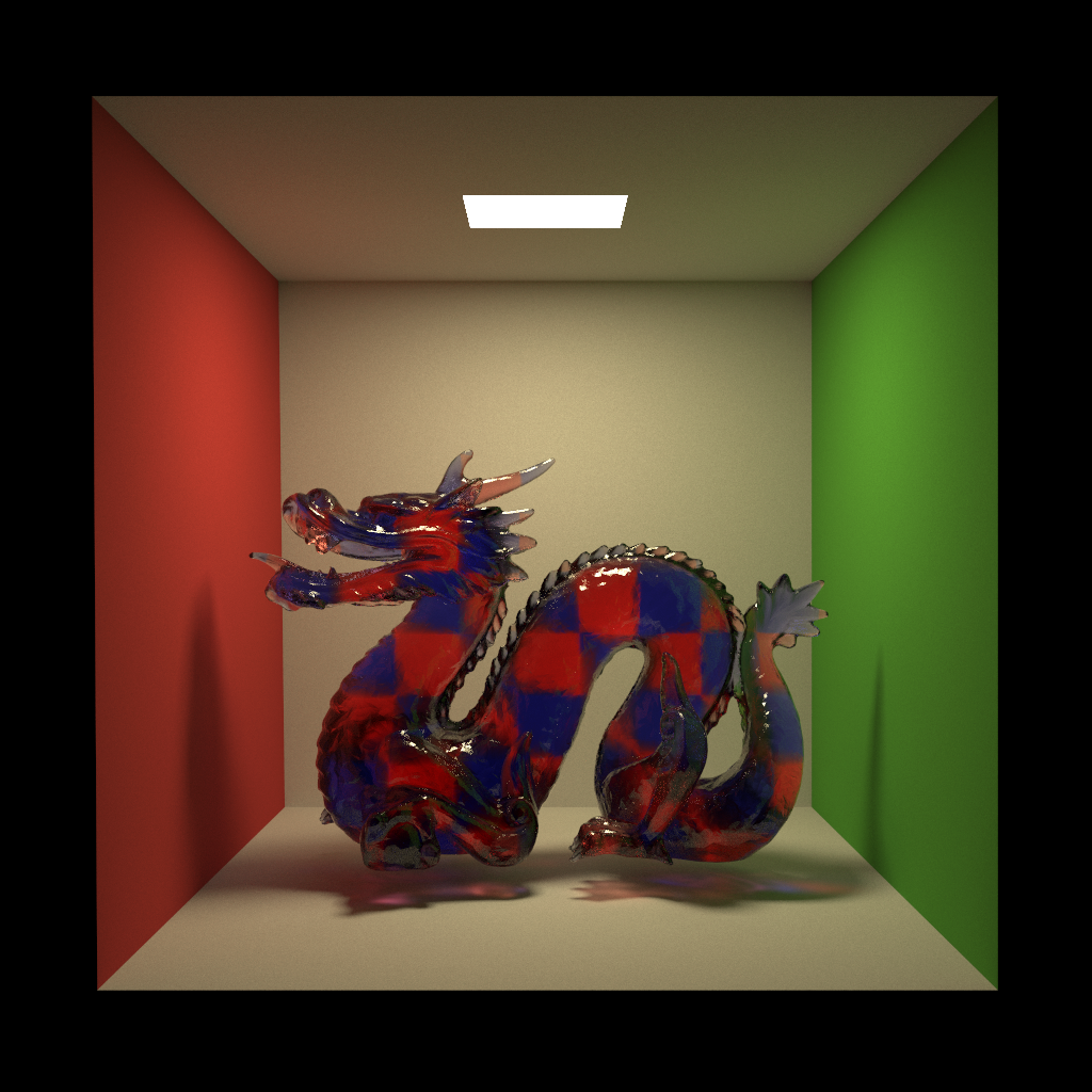
Adding previous hit information and ray march support to my BSDF system was a very straightforward task. I also added volumetric data support to Takua, allowing for the following attenuation test with a glass Stanford Dragon filled with a checkerboard red and blue medium. The red and blue medium is ray marched through to calculate the total attenuation. Note how the thinner parts of the dragon allow more light through resulting in a lighter appearance, while thicker parts of the dragon attenuate more light resulting in a darker appearance. Also note the interesting red and blue caustics below the dragon:
Things got much more complicated once I added support for what I call “deep attenuation”- that is, attenuation through multiple mediums embedded inside of each other. A simple example is an ice cube floating in a glass of liquid, which one might model in the following way:
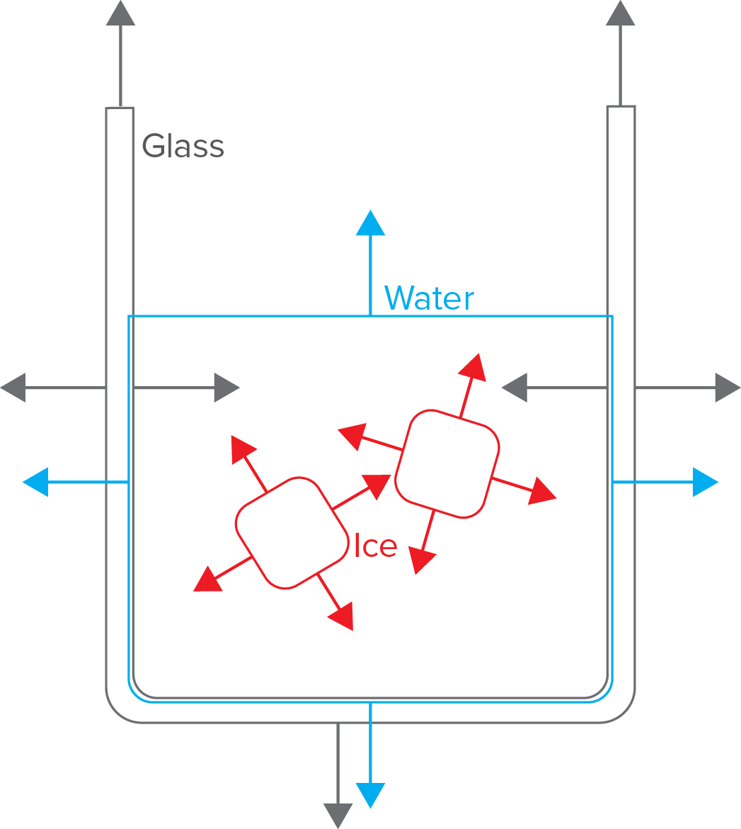
There are two things in the above diagram that make deep attenuation difficult to implement. First, note that the ice cube is modeled without a corresponding void in the liquid- that is, a ray path that travels through the ice cube records a sequence of intersection events that goes something like “enter water, enter ice cube, exit ice cube, exit water”, as opposed to “enter water, exit water, enter ice cube, exit ice cube, enter water, exit water”. Second, note that the liquid boundary is actually slightly inside of the inner wall of the glass. Intuitively, this may seem like a mistake or an odd property, but this is actually the correct way to model a liquid-glass interface in computer graphics- see this article and this other article for details on why.
So why do these two cases complicate things? As a ray enters each new medium, we need to know what medium the ray is in so that we can execute the appropriate BSDF and get the correct attenuation for that medium. We can only evaluate the attenuation once the ray exits the medium, since attenuation is dependent on how far through the medium the ray traveled. The easy solution is to simply remember what the BSDF is when a ray enters a medium, and then use the remembered BSDF to evaluate attenuation upon the next intersection. For example, imagine the following sequence of intersections:
- Intersect glass upon entering glass.
- Intersect glass upon exiting glass.
- Intersect water upon entering water.
- Intersect water upon exiting water.
This sequence of intersections is easy to evaluate. The evaluation would go something like:
- Enter glass. Store glass BSDF.
- Exit glass. Evaluate attenuation from stored glass BSDF.
- Enter water. Store water BSDF.
- Exit water. Evaluate attenuation from stored water BSDF.
So far so good. However, remember that in the first case, sometimes we might not have a surface intersection to mark that we’ve exited one medium before entering another. The following scenario demonstrates how this first case results in missed attenuation evaluations:
- Intersect water upon entering water.
- Exit water, but no intersection!
- Intersect ice upon entering ice.
- Intersect ice upon exiting ice.
- Enter water again, but no intersection either!
- Intersect water upon exiting water.
The evaluation sequence ends up playing out okay:
- Enter water. Store water BSDF.
- Exit water, but no intersection. No BSDF evaluated.
- Enter ice. Intersection occurs, so evaluate attenuation from stored water BSDF. Store ice BSDF.
- Exit ice. Evaluate attenuation from stored ice BSDF.
- Enter water again, but no intersection, so no BSDF stored.
- Exit water…. but there is no previous BSDF stored! No attenuation is evaluated!
Alternatively, in step 6, instead of no previous BSDF, we might still have the ice BSDF stored and evaluate attenuation based on the ice. However, this result is still wrong, since we’re now using the ice BSDF for the water.
One simple solution to this problem is to keep a stack of previously seen BSDFs with each ray instead of just storing the previously seen BSDF. When the ray enters a medium through an intersection, we push a BSDF onto the stack. When the ray exits a medium through an intersection, we evaluate whatever BSDF is on the top of the stack and pop the stack. Keeping a stack works well for the previous example case:
- Enter water. Push water BSDF on stack.
- Exit water, but no intersection. No BSDF evaluated.
- Enter ice. Intersection occurs, so evaluate water BSDF from top of stack. Push ice BSDF on stack.
- Exit ice. Evaluate ice BSDF from top of stack. Pop ice BSDF off stack.
- Enter water again, but no intersection, so no BSDF stored.
- Exit water. Intersection occurs, so evaluate water BSDF from top of stack. Pop ice BSDF off stack.
Excellent, we now have evaluated different medium attenuations in the correct order, haven’t missed any evaluations or used the wrong BSDF for a medium, and as we exit the water and ice our stack is now empty as it should be. The first case from above is now solved… what happens with the second case though? Imagine the following sequence of intersections where the liquid boundary is inside of the two glass boundaries:
- Intersect glass upon entering glass.
- Intersect water upon entering water.
- Intersect glass upon exiting glass.
- Intersect water upon exiting water.
The evaluation sequence using a stack is:
- Enter glass. Push glass BSDF on stack.
- Enter water. Evaluate glass attenuation from top of stack. Push water BSDF.
- Exit glass. Evaluate water attenuation from top of stack, pop water BSDF.
- Exit water. Evaluate glass attenuation from top of stack, pop glass BSDF.
The evaluation sequence is once again in the wrong order- we just used the glass attenuation when we were traveling through water at the end! Solving this second case requires a modification to our stack based scheme. Instead of popping the top of the stack every time we exit a medium, we should scan the stack from the top down and pop the first instance of a BSDF matching the BSDF of the surface we just exited through. This modified stack results in:
- Enter glass. Push glass BSDF on stack.
- Enter water. Evaluate glass attenuation from top of stack. Push water BSDF.
- Exit glass. Evaluate water attenuation from top of stack. Scan stack and find first glass BSDF matching the current surface’s glass BSDF and pop that BSDF.
- Exit water. Evaluate water attenuation from top of stack. Scan stack and pop first matching water BSDF.
At this point, I should mention that pushing/popping onto the stack should only occur when a ray travels through a surface. When the ray simply reflects off of a surface, an intersection has occurred and therefore attenuation from the top of the stack should still be evaluated, but the stack itself should not be modified. This way, we can support diffuse inter-reflections inside of an attenuating medium and get the correct diffuse inter-reflection with attenuation between diffuse bounces! Using this modified stack scheme for attenuation evaluation, we can now correctly handle all deep attenuation cases and embed as many attenuating mediums in each other as we could possibly want.
…or at least, I think so. I plan on running more tests before conclusively deciding this all works. So there may be a followup to this post later if I have more findings.
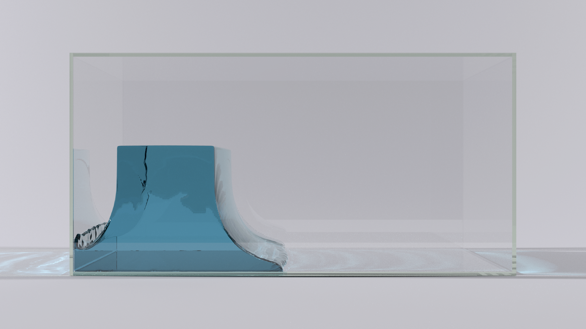
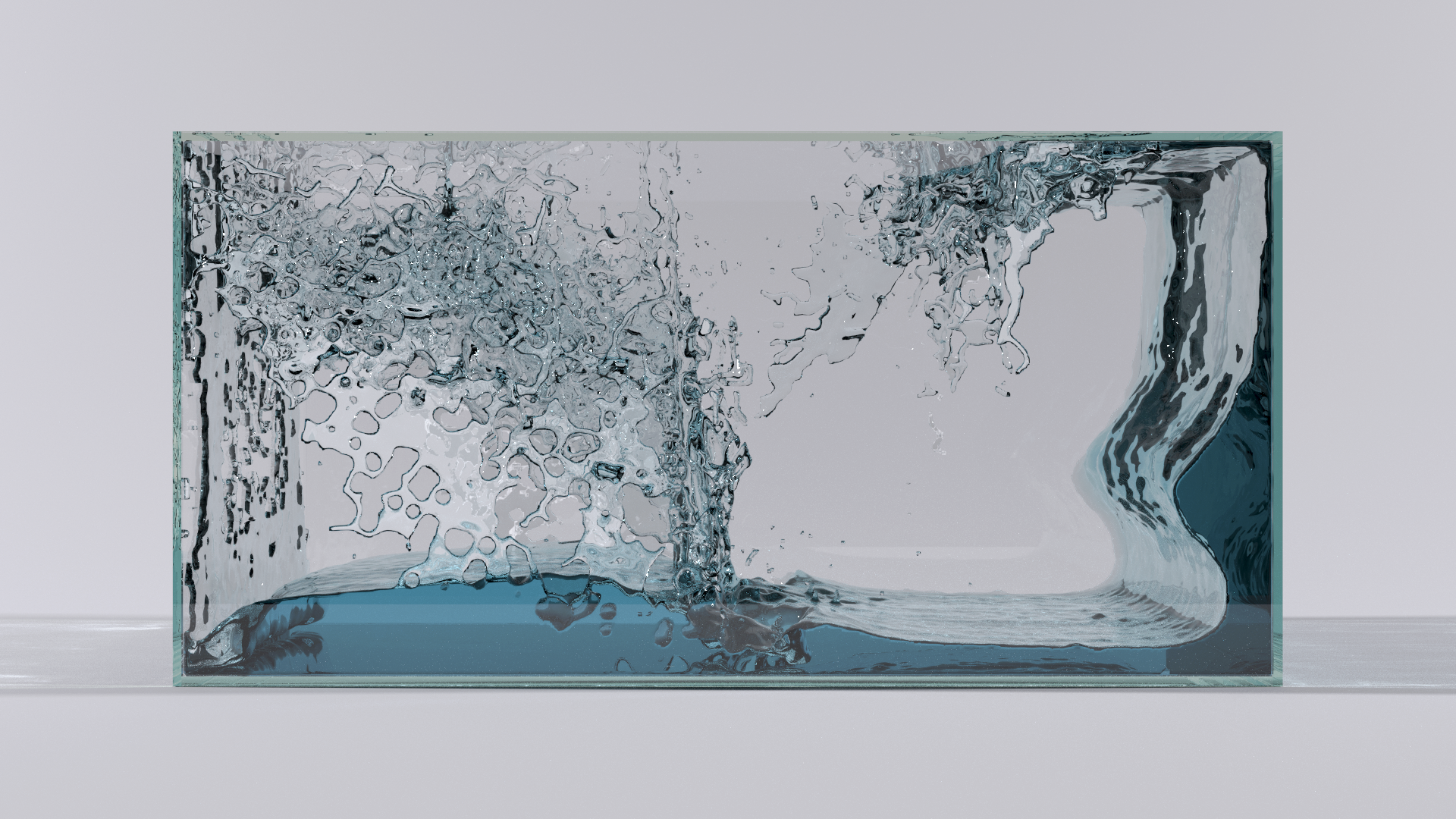
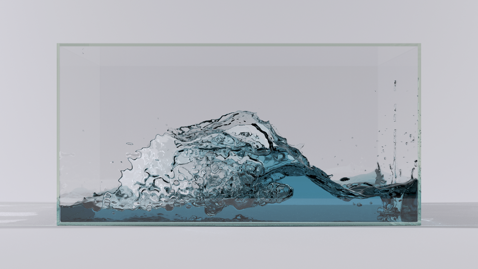
A while back, I wrote a PIC/FLIP fluid simulator. However, at the time, Takua Renderer didn’t have attenuation support, so I wound up rendering my simulations with Vray. Now that Takua a0.5 has robust deep attenuation support, I went back and used some frames from my fluid simulator as tests. The image at the top of this post is a simulation frame from my fluid simulator, rendered entirely with Takua a0.5. The water is set to attenuate red and green light more than blue light, resulting in the blue appearance of the water. In addition, the glass has a slight amount of hazy green attenuation too, much like real aquarium glass. As a result, the glass looks greenish from the ends of each glass plate, but is clear when looking through each plate, again much like real glass. Here are two more renders: